 |
|
 |
|
'FQ' Series Cavity Filters |
 'FQ' Series
Q-Circuit Filters 'FQ' Series
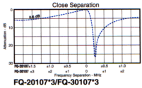
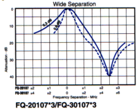
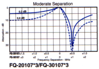
Q-Circuit FiltersThese filters employ the Sinclair-developed Q-circuit design. The operation of the Q-circuit is such that it inverts the characteristics of a standard notch filter, and uses the narrow resonance notch to create the circuit passband while allowing the lower Q elements, such as the loop and its reactance adjustment, to produce the relatively broad isolation notch.  In this manner, optimum
use of the cavity components is realized, resulting in close pass/reject spacing, low
insertion loss, and broad isolation notch. The filters can be tuned for either high or low
pass condition, with minimum frequency separations. In this manner, optimum
use of the cavity components is realized, resulting in close pass/reject spacing, low
insertion loss, and broad isolation notch. The filters can be tuned for either high or low
pass condition, with minimum frequency separations. The Q-circuit filter combines the features of a
bandpass and reject filter. This can be particularly useful when a close frequency might
interfere with the desired frequency. For this reason, both the pass and reject
frequencies and required insertion loss must be specified when ordering Q-circuit filters. The Q-circuit filter combines the features of a
bandpass and reject filter. This can be particularly useful when a close frequency might
interfere with the desired frequency. For this reason, both the pass and reject
frequencies and required insertion loss must be specified when ordering Q-circuit filters.
|
SPECIFICATIONS |
| Electrical (Specifications) | |||||
FQ-20107*2 |
FQ-20107*3 |
FQ-30107*3 |
FQ-40137*3 |
||
| Frequency Range | MHz |
132-150 | 138-174 | 406-512 | 806-960 |
| Frequency Separation | |||||
| Pass Band Insertion Loss | See Curves | ||||
| Attenuation | dB | See Curves | |||
| Maximum Input VSWR (Note1) |
1.5:1 | ||||
| Maximum Input Power | Watts | 350 | |||
| Termination | 'N' Female | ||||
| Temperature Range | -40�C to +60�C | ||||
| Note:1- VSWR is referenced to 50 ohms. VSWR varies with
insertion loss setting. 2- Specify transmit and receive frequencies when ordering. If unspecified, filters will be supplied untuned. |
| Mechanical Specifications | |||||
FQ-20107*2 |
FQ-20107*3 |
FQ-30107*3 |
FQ-40137*3 |
||
| Height | in (mm) | 36 (914) |
32.5 (826) |
16.6 (442) | 16.7 (424) |
| Width | in (mm) | 7.0(178) | |||
| Depth | in (mm) | 7.0(178) | |||
| Weight | lb (kg) | 11 (4.90) | 10 (4.54) | 6 (2.72) | 5.5 (2.5) |
|
WISCO International, Inc. -
MIAMI, FL U.S.A. Fax: (954) 370-3997 | E-mail: wiscointl@wiscointl.com |