|
|
|
|
|
MODEL 66 |
|
The Zetron Model 66 Transmitter
Controller connects to a radio paging transmitter to provide remote
control from a central paging terminal. Using positive action tone
control methods, the Model 66 recognizes its site address, selects
the transmitter modulation mode (analog or digital), keys the paging
transmitter, and transmits the paging audio or digital data. The Model 66 is also recommended for in-plant type applications where a single transmitter is located more than 30 feet from the paging terminal. The Model 66 provides electrical isolation which reduces risk of data corruption or damage to the interfaces due to noise. It also reduces the installation costs because only a two-wire interface is needed between the paging terminal and the transmitter location.
SYSTEM ARCHITECTURE Any paging terminal or control equipment that generates the Motorola PURC tones can interface to the Model 66. The Model 66 makes other types of transmitters compatible with Motorola PURC systems. Model 33 Paging Network Controller Paging Links Positive Tone one Control DIGIT DIGITAL AL PAGING Alerting binary digital pagers and
sending display messages (such as to POCSAG and Golay type pagers)
require more sophisticated equipment than does simpler tone + voice
paging. SITE ADDRESSING OPTIONS Wide-area paging systems can be designed to avoid the expense of simulcast equipment. By arranging the geographical paging area into zones that do not overlap, the central paging terminal can select each zone in sequence and reach all paging subscribers. With an optional address decoder board, multiple transmitters in a single zone can be addressed. Transmitter Address Decoder Board
Option Dual-Frequency Address Decoder
Board Option SHARED CHANNELS Some paging channels are shared for
use by co-channel carriers or mobile subscribers. In these systems,
it is SIMULCAST DELAY MODULE OPTION Simulcast operation requires the signals transmitted by each transmitter be very close to each other in frequency at all times. To accomplish this, the transmitters are locked to common references or have extremely high stability oscillators and exactly the same audio modulation characteristics. The optional Simulcast Delay Module assures that audio modulation is identical for each transmitter by delaying the audio signals by the amount necessary to compensate for different link propagation paths. Accurate Delays MODEL 66 LINK CONTROLLER The Model 66 Link Controller is
similar to the Model 66 except that it is used to control remote
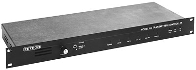
link transmitters INSTALLATION AND MAINTENANCE The rack-mount package, low power consumption, and careful RF-filtered design of the Model 66 make it ideal for mounting in the radio transmitter equipment rack. Modular screw terminal connectors provide compatibility with any cabling system. Front panel level adjustments, indicator lamps, disable switch, and built-in monitor speaker simplify maintenance. Features
|
|
Specifications |
|
GENERAL |
|
| Site Addressing | All call (standard) 30-site addressing (option) |
| Tone Protocol | Motorola PURC�
compatible Dropout prevention Time-out timer selectable (1.1, 2.3, 4.5, 9.1 minutes) Special guard tones available for HSC paging compatibility |
| Digital Paging | Built-in 202-type modem |
| Front Panel Lamps | Power, Audio, Digital, PTT, COR/CAS |
| Adjustments | TX level, Link in level, Link out level Accessible from front panel |
| Link Audio Monitor | Built-in amplified speaker Adjustable level |
| Service Switch | Normal, Disable/Reset |
| Power Requirements | 12-14V DC, 350mA maximum or 9-12V AC, 350mA maximum or 120/240 V AC, 50/60 Hz adaptors |
| Operating Temp. | 30 to 130 degrees Fahrenheit |
| Size | 1.75"H x 19"W x 6.75"D Rack-mountable |
| Weight | 4 lb. maximum |
| SIMULCAST DELAY BOARD | |
| Touch Tone or RS-232 Control |
Addressable: 00 to 98 Zone / Quiet Control 0 to 9 Universal address:99 |
| Security: | 8 character sequences disable and enable control. Set individually or universally. |
| Frequency Range | 56 Hz to 3400 Hz |
| Delay Range | 300 to 2,000,000 microseconds in 1 microsecond steps |
| Gain Range | -6 dB to +6 dB, 0.1 dB steps |
| Input Impedance | 10K Ohm - Unbalanced |
| Output Impedance | Low Z - Unbalanced |
| Nonlinear Distortion | Less than 1% |
| Noise | Less than -60 dBmC |
| TRANSMITTER INRTERFACE | |
| Audio Output | Balanced 600-ohm Adjustable -30 to 0 dBmj |
| Control Relays | 1 Amp rating at 26 V AC PTT analog SPDT PTT digital SPDT |
| Digital Data | Bipolar RS-232 Polarity jumper selectable |
| Digital Mode | Bipolar RS-232 Polarity jumper selectable |
| CAS/COR Input | Voltage level or contact closure 0.5V threshold Polarity jumper selectable |
| Connector | Detachable screw terminal stripw |
| LINK INTERFACE | |
| Audio Input | Paging tones/data, control tones Balanced 600-ohm Adjustable -30 to +10 dBmn |
| Audio Output | Channel busy tone
(option) Balanced 600-ohm Adjustable -20 to 0 dBm Reverse 202 modem channel |
| Connector | Detachable screw terminal stripw |
|
WISCO International, Inc. -
MIAMI, FL U.S.A. Fax: (954) 370-3997 | E-mail: wiscointl@wiscointl.com |